In modern audio system design, MEMS (Micro-Electro-Mechanical Systems) microphones have largely replaced traditional analog microphones—thanks to their tiny size, low power consumption, and robust performance. One of their greatest advantages is the digital output, which simplifies integration and improves noise immunity. In this article, we’ll explore the two most common digital interfaces for MEMS microphones, compare their characteristics, and show how to choose the right format for your application.
1. Why Digital Output Matters
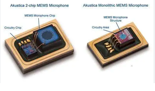
Unlike analog microphones, which output a variable voltage that must be routed through anti-aliasing filters and an external ADC (Analog-to-Digital Converter), digital MEMS microphones integrate the ADC on-chip. This yields:
- Superior EMI Immunity
The signal is digitized right at the diaphragm, so it isn’t corrupted by electromagnetic noise along the PCB traces. - Simplified PCB Layout
No need for precision analog routing or additional filtering components. - Consistent Performance
Tight factory calibration of the ADC ensures minimal part-to-part variation.
2. The Two Main Digital Interfaces
2.1 PDM (Pulse Density Modulation)
- How It Works: Outputs a one-bit high-rate stream whose density corresponds to the sound pressure level.
- Clocking: Requires a single clock line (typically 1–3 MHz).
- Pros:
- Very simple interface
- Low pin count
- Cons:
- Requires significant MCU/DSP processing to decimate and filter
- May need careful PCB layout for high-speed clock
2.2 I²S (Integrated Inter-IC Sound)
- How It Works: Sends multi-bit digital audio words (usually 16–24 bits) synchronized by a word select and bit clock.
- Clocking: Two or three lines: Bit Clock (BCLK), Word Select (WS), and optionally Master Clock (MCLK).
- Pros:
- High audio resolution without extra filtering
- Native support in many audio codecs and DSPs
- Facilitates multi-mic synchronization
- Cons:
- More pins required
- Slightly higher BOM and routing complexity
3. Choosing Between PDM and I²S
| Criterion | PDM | I²S |
|---|---|---|
| Pin Count | Low (Data + Clock) | Higher (BCLK + WS [+ MCLK]) |
| Processing Load | High (decimation/filter in firmware) | Low (direct multi-bit data) |
| Audio Quality | Depends on decimation filter design | Native high-bit resolution |
| Multi-Mic Arrays | Possible, but complex | Easier sync via shared clocks |
Use PDM when you need the simplest hardware interface and have plenty of processing headroom to filter the data stream in software.
Use I²S when you need higher resolution audio, easier synchronization between multiple microphones, or compatibility with standard audio peripherals.
4. SISTC’s MEMS Microphones with Digital Output
At Wuxi Silicon Source Technology Co., Ltd., our digital MEMS microphones support both PDM and I²S interfaces, offering designers maximum flexibility:
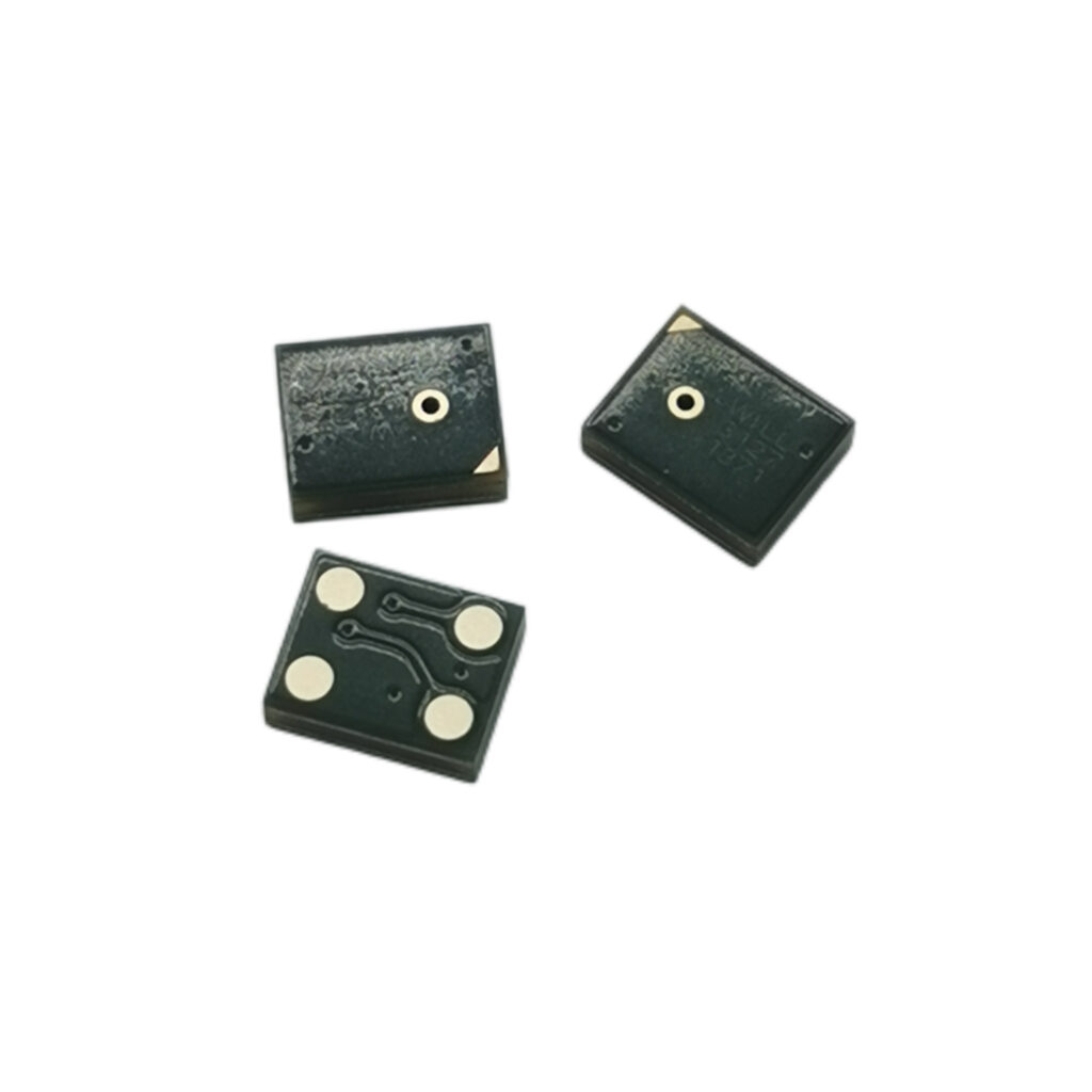
- DM2611 Digital MEMS Microphone
• SNR: 64 dB | AOP: 125 dB SPL | Interfaces: PDM & I²S - DM4710 Ultra-Low Power MEMS Microphone
• Operating Current: 12 µA | SNR: 62 dB | Interfaces: PDM & I²S
Whether you’re building smart speakers, wearables, or automotive voice-control systems, these parts deliver reliable digital audio that’s easy to integrate.
5. Further Reading
- PDM vs. I²S: Choosing the Right Digital Microphone Interface – Analog Devices technical brief¹
- MEMS Microphone Fundamentals – TDK InvenSense whitepaper²
¹ https://www.analog.com/en/technical-articles/understanding-pdm-and-i2s-interfaces.html
² https://www.invensense.tdk.com/technology/mems-microphones/