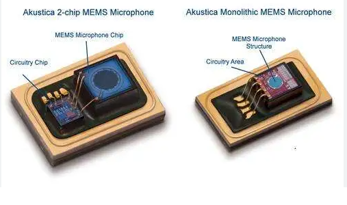
High-performance MEMS microphones have become essential components in smartphones, tablets, and laptops, offering compact size, high sensitivity, and low power consumption. However, their integration into modern consumer electronics presents a unique design challenge: the acoustic path.
Because microphone sound ports are often hidden within a device’s enclosure, engineers must design an efficient acoustic channel to transmit external sound waves to the microphone’s diaphragm. This acoustic path design plays a critical role in determining the microphone’s overall frequency response and system-level audio quality.
🔗 View high-performance MEMS microphones from SISTC:
👉 https://sistc.com/product-category/mems-microphone/
What Is the Acoustic Path?
The acoustic path includes:
- The external housing of the product
- Acoustic gaskets or sealing rings
- The sound hole on the PCB
- The microphone port structure
Together, these components form a waveguide that determines how sound propagates into the sensor. Materials, dimensions, and geometry all influence how acoustic energy is transmitted, reflected, or dampened along the path.
Helmholtz Resonance: A Key Acoustic Principle
One critical concept in acoustic design is the Helmholtz resonator. When a small sound port (neck) is connected to an air cavity (chamber), the system forms a resonant structure—similar to the sound produced by blowing across the opening of a bottle.
The resonance frequency (f₀) can be approximated using:
f₀ = (c / 2π) * √(A / (L × V))
Where:
c= speed of sound in airA= cross-sectional area of the portL= effective length of the portV= volume of the cavity
While this model provides a good starting point, real-world acoustic paths are far more complex, requiring precise 3D modeling and simulation.
📘 Learn more: COMSOL Acoustic Simulation Resources
Key Design Variables in the Acoustic Path
Several parameters can be tuned to optimize frequency response:
| Parameter | Impact on Performance |
|---|---|
| Gasket thickness | Increases path length; may reduce high-frequency gain |
| Gasket inner diameter | Larger diameter raises resonance frequency |
| Sound hole diameter (PCB/housing) | Affects impedance and Helmholtz resonance behavior |
| Path curvature or bends | May introduce phase distortion or attenuation |
| Material acoustic impedance | Impacts sound energy loss along the path |
By using acoustic simulation tools such as COMSOL Multiphysics, engineers can evaluate how each of these variables influences real-world system behavior.
Low vs. High Frequency Performance
- Low-frequency response is determined primarily by the sensor’s vent hole geometry and the back chamber volume
- High-frequency response is influenced by the front chamber and sound port, including any resonance from the Helmholtz structure
📌 For example, the SISTC WBC3526DB26TJ0 positions the transducer directly above the port, reducing front chamber volume and enabling improved high-frequency sensitivity.
Case Example: How Gasket Dimensions Affect Frequency Response
- Thicker gaskets extend the acoustic path, potentially damping high-frequency signals
- Wider inner diameter increases the acoustic aperture, shifting resonance to higher frequencies
- Bends and abrupt changes in the path can introduce additional resonance peaks or dips, requiring careful simulation
Engineers can use virtual prototyping to fine-tune these variables and achieve a flat or tailored frequency response for specific product use cases.
Conclusion
MEMS microphone integration isn’t just about selecting the right sensor—it’s about designing an acoustic path that preserves and enhances the microphone’s performance across a wide frequency range.
By applying acoustic modeling, Helmholtz theory, and high-fidelity simulation tools, product teams can:
- Ensure optimal sensitivity across low and high frequencies
- Reduce undesired resonances or notches
- Improve overall voice quality and user experience
🎯 Explore SISTC’s precision MEMS microphones built for consumer electronics:
👉 https://sistc.com/product-category/mems-microphone/