

Sound Port Geometry, Sealing, Vibration Isolation & Anti-Resonance Best Practices
Author: Wuxi Silicon Source Technology Co., Ltd. (SISTC)
Version: 1.0 (Public White Paper)
Category: Explore / Acoustic Engineering / MEMS Microphone Array Design
Executive Summary
In microphone array products—smart speakers, conference systems, dashcams, smart home controllers, and industrial voice terminals—acoustic cavity design is one of the most underestimated drivers of real-world performance.
Even when the MEMS microphone itself meets excellent datasheet specifications (SNR, sensitivity, AOP, phase matching), the final product can still suffer from:
- random ringing/buzzing noise due to structural vibration coupling
- unexpected high-frequency peaks caused by Helmholtz resonance
- degraded wake-word performance due to leakage and inconsistent sealing
- beamforming instability due to non-uniform acoustic paths
This white paper provides practical structural design rules for acoustic cavities, sound ports, sealing, damping, and array layout, helping engineering teams shorten development cycles and avoid costly re-spins.
SISTC has been focused on MEMS microphone design and manufacturing for 15+ years, with strong capabilities in audio pickup technology, noise reduction algorithms, and hardware-software integration for acoustic systems.
1. Why Acoustic Cavity Design Matters
An acoustic cavity is not just a “hole” in the enclosure. It forms a controlled acoustic path between the external sound field and the microphone inlet.
In array systems, the acoustic cavity must achieve two objectives simultaneously:
- Maximum direct pickup with minimal distortion or frequency coloration
- Consistency across microphones, enabling stable beamforming and accurate phase alignment
In practice, poor cavity design often causes bigger performance loss than the microphone itself.
2. MEMS Microphone Selection Requirements (for Array Applications)
Before structural design begins, the microphone model must match array requirements. SISTC recommends the following baseline specifications for array products:
- Sensitivity: > -40 dBV @ 94 dB SPL, 1 kHz
- SNR: ≥ 65 dB
- AOP: ≥ 120 dB SPL
- THD: ≤ 1% @ 1 kHz
- Phase coherence: < 3°
- Omnidirectional pickup pattern
- Frequency response variation: < 2 dB (100 Hz–8 kHz)
3. Sound Port & Acoustic Cavity Geometry (Core Rules)
3.1 The L/D Rule: The Most Practical Design Metric
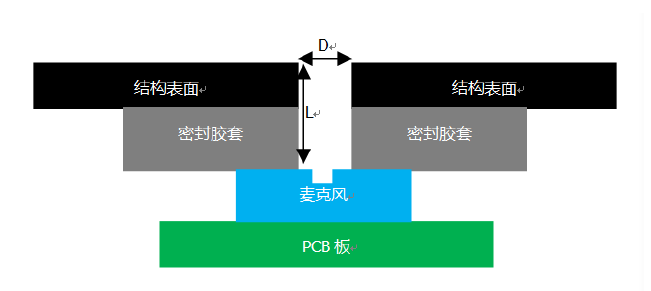
A sound port is essentially a short acoustic tube. Its geometry is defined by:
- L = depth of the sound port (or cavity length)
- D = diameter of the sound port opening
SISTC recommendation:
- D > 1.0 mm
- L < 5.0 mm
- L/D < 3 (critical guideline)
This means:
- keep the port as wide as possible
- keep the cavity as shallow as possible
Why it works:
A smaller L and larger D reduces acoustic impedance and minimizes unwanted resonant behavior, leading to smoother frequency response and better sensitivity stability.
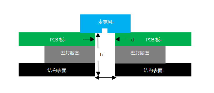
3.2 PCB Sound Hole Size (Bottom-Port MEMS)
For bottom-port microphone structures, the PCB hole must match microphone sealing ring constraints.
Current common sealing ring inner diameters:
- 0.6 mm
- 1.0 mm
Considering manufacturing tolerance, recommended PCB apertures:
- for 0.6 mm ring → PCB hole 0.4 mm
- for 1.0 mm ring → PCB hole 0.8 mm
When PCB thickness exceeds 1.0 mm, prioritize microphones with 1.0 mm sealing ring for better manufacturability and sealing reliability.
4. Avoiding Helmholtz Resonance (Most Common Root Cause)
4.1 What is Helmholtz Resonance?
A Helmholtz resonator forms when a cavity volume connects to the outside through a narrow neck—similar to blowing across a bottle opening.
In microphone products, this typically happens when:
- the port is too narrow/too long
- the cavity behind the microphone inlet is too large
- sealing is inconsistent and creates unintended volumes
4.2 Why it is Dangerous
Helmholtz resonance often creates:
- high-frequency spikes
- frequency response ripple
- unstable acoustic performance across samples
SISTC explicitly recommends:
Avoid creating Helmholtz resonator structures, both for top-port and bottom-port designs.
Engineering checklist to avoid it:
- follow L/D < 3
- avoid narrow channels
- eliminate unnecessary internal voids near the inlet
- ensure consistent sealing so the cavity volume does not vary by assembly
5. Sealing, Gaskets, and Leakage Control
5.1 Uniformity is Mandatory in Arrays
For array products, each microphone must experience the same acoustic environment.
SISTC recommendation:
- every microphone housing must be designed and installed identically
- use silicone, gaskets, or foam seals between:
- panel and PCB
- silicone microphone and structure
5.2 Practical Sealing Principles
- ensure direct vocal pickup at the sound hole and equal distribution to each microphone
- prevent the sound holes from being blocked
- use sealing materials that remain stable over temperature and aging
- design for manufacturing tolerances (avoid borderline dimensions)
6. Vibration Isolation & Mechanical Noise Suppression
In real products, random ringing/buzzing often comes from mechanical coupling, not from the MEMS microphone.
6.1 Isolation Recommendations
- microphone should be isolated from firmware/structure surfaces using silicone sleeve
- avoid hard contact between microphone and enclosure
- silicone thickness around the microphone should be > 3 mm
6.2 Positioning Guidelines
- keep microphones away from vibration or interference sources
- isolate from solid surfaces to reduce vibration transmission and improve sealing
7. Dust Filter / Dust Cover Design
For products where the microphone pickup hole faces upward:
- add a dust cover to prevent long-term dust accumulation
- select a filter with:
- flat frequency response
- minimal transmission loss
Tip: in mass production, dust cover selection should include acoustic verification across temperature and humidity conditions.
8. Microphone Array Layout Recommendations
Acoustic cavity design must work together with array geometry.
8.1 Line Array
- all microphones face the same direction
- all inlet ports aligned on a straight line
Recommended spacing:
- 2–4 mic line array: 30–60 mm
- 5–6 mic line array: 21.3–50 mm
- best practice: 30–40 mm
8.2 Circular Array
Recommended radius:
- 30–40 mm
9. Speaker Interaction (If Product Includes Speaker)
When speaker + microphone coexist, acoustic cavity design must prevent speaker energy from coupling into microphones.
SISTC recommendations:
- implement internal sound insulation between MIC and SPK
- distance between MIC pickup port and SPK outlet: ≥ 100 mm
- ensure MIC and SPK ports are ideally 90° (not aligned)
- keep speaker-to-microphone SPL below 90 dB at MIC position
- voice-to-speaker SNR at MIC should not be less than -25 dB
10. How SISTC Supports Customer Acoustic Cavity Design
During the structural design phase, SISTC recommends customers share:
- microphone datasheet
- amplifier / codec / speaker datasheet
- structural drawings
Our engineering team can assist with:
- acoustic cavity and sound port review
- sealing and tolerance evaluation
- array geometry validation
- risk analysis for resonance and vibration noise
- prototype tuning and acoustic testing guidance
Conclusion
A successful microphone array product depends on system-level acoustic engineering, not only microphone selection.
By following key design rules such as:
- L/D < 3
- avoid Helmholtz resonators
- strict sealing uniformity
- silicone isolation > 3 mm
- proper dust filtering and array spacing
engineering teams can significantly improve:
- wake-word robustness
- beamforming stability
- frequency response consistency
- mass production yield
Call to Action
If you are designing a microphone array product and want SISTC to review your acoustic cavity and sound port structure, contact our team:
- Website: https://www.sistc.com
- Product page (internal link): Smart MEMS Microphone
See also
- Wikipedia – Helmholtz resonance
https://en.wikipedia.org/wiki/Helmholtz_resonance