All MEMS microphones are inherently omnidirectional, meaning they respond equally to sound from all directions. However, when multiple microphones are arranged into an array, it is possible to shape directional sensitivity—known as beamforming.
Beamforming enables microphone arrays to respond more strongly to sound from certain directions while suppressing others. This guide introduces the basic principles and array types used in beamforming, focusing on broadside and endfire arrays, including spatial and frequency responses, design trade-offs, and sensitivity considerations.
Microphone Directionality and Polar Patterns
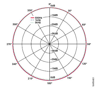
Directionality refers to how a microphone’s output level varies depending on the sound source’s position in an anechoic space. As shown in Figure 1, all MEMS microphones from ADI are omnidirectional and provide a circular polar response.
- On-axis: 0°, the intended sound pickup direction
- Off-axis: 90°, 180°, 270°—side and rear
- All polar diagrams in this guide are normalized to the 0° response
Frequency and Wavelength Relation
The relation between sound speed, frequency, and wavelength is:
c = f × λ, where c ≈ 343 m/s in air at 20°C.
See Figure 1 for a frequency-wavelength reference chart.
Broadside Microphone Arrays
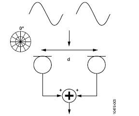
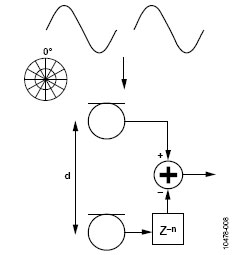
A broadside array places microphones in a line perpendicular to the incoming sound wave direction (see Figure 2). These are ideal when the desired sound source is located directly in front of the microphone array.
- Mic spacing: d
- Signal processing: simple summation
- Benefit: Strong side-lobe suppression (90°, 270°)
- Limitation: No discrimination between front and back (0° vs. 180°)
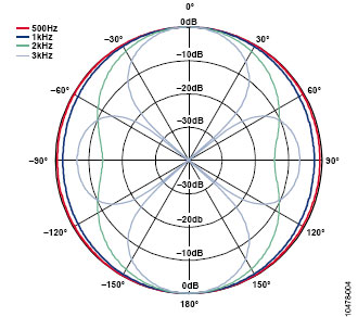
In a two-mic broadside array with 75 mm spacing, destructive interference occurs at ~2.3 kHz, where the half wavelength equals mic spacing.
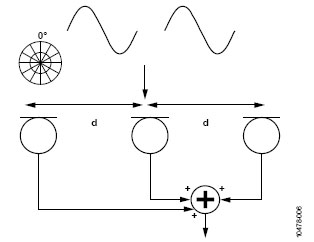
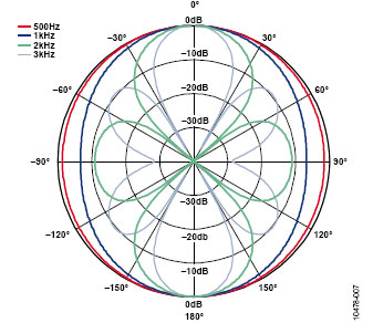
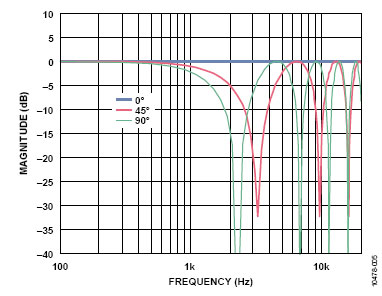
At higher frequencies, spatial aliasing occurs, introducing new nulls at unwanted angles (see Figure 3). Increasing mic count improves side rejection (see Figures 4–5) but reduces the frequency threshold for aliasing.
Broadside Frequency Response
The on-axis response remains flat as signals are summed coherently. Off-axis attenuation varies with frequency and mic spacing (see Figure 6). Design trade-off: wider spacing improves low-frequency directionality but increases aliasing risk.
Endfire (Axial) Arrays and Differential Beamformers
An endfire array aligns microphones in the same direction as the desired sound path (see Figure 7). The differential configuration subtracts the delayed signal from the rear mic from the front mic to create cardioid, supercardioid, or hypercardioid patterns.
- Key design variables:
- Mic spacing
- Delay time (based on sampling rate)
- For fs = 48 kHz, one-sample delay ≈ 21 µs, which corresponds to ~7 mm in air
- Cardioid response is achieved when delay matches physical time-of-arrival offset (see Figure 9)
Frequency Response and Nulls
- Differential arrays exhibit high-pass behavior
- Output increases at 6 dB/octave up to the null frequency (half wavelength = spacing)
- Aliasing and additional nulls appear at higher frequencies (see Figures 10–12)
The mic spacing and delay time determine the null position and response shape:
- Too short → weak null
- Too long → split rear nulls (see Figure 11)
Applying equalization (EQ) is recommended to flatten the passband. Selecting an appropriate null frequency is critical—too low interferes with speech, too high weakens low-frequency sensitivity.
Higher-Order Endfire Arrays
By adding more aligned microphones, higher-order beamformers can be constructed (see Figure 13). A 2nd-order endfire array (3 mics) provides stronger side-lobe suppression (12 dB) versus 1st-order (6 dB), as shown in Figure 14.
More elements improve performance but require longer physical arrays, which may conflict with industrial design constraints.
Microphone Matching
High-performance beamforming demands tight matching of microphone sensitivity and frequency response. Discrepancies degrade null performance and directionality. MEMS microphones from ADI, for example, are tightly matched for this purpose.
System SNR and Beamforming Impact
Beamforming affects system signal-to-noise ratio (SNR):
- Broadside arrays improve on-axis SNR by summing signals:
- +6 dB signal increase
- +3 dB noise increase (uncorrelated noise)
- Net SNR improvement: +3 dB
- Off-axis SNR degrades due to decreased signal level
- Differential arrays have complex SNR behavior depending on frequency and mic spacing
Array Geometry and Placement
Mic center-to-center spacing is not the only consideration—PCB thickness and mic height affect true acoustic center placement. For example, the acoustic center of an ADI MEMS mic lies 0.57 mm above the port. This must be accounted for if mics are mounted on different levels.
Advanced Beamforming
This guide focuses on basic beamforming. Advanced algorithms such as:
- Beam steering
- Source tracking
- Non-uniform spacing
- FFT-based adaptive processing
…can provide robust performance with minimal hardware. High-order beamformers using non-uniform spacing can achieve wider frequency range and lower noise.
Summary: Broadside vs. Endfire Arrays
| Feature | Broadside Array | Endfire Array |
|---|---|---|
| Main direction | Perpendicular | Aligned with sound path |
| Null location | Side (90°, 270°) | Rear (180°) |
| Best use case | Wall-mounted speakers | Smart assistants, headsets |
| Frequency behavior | Flat, wide bandwidth | High-pass with EQ needed |
| Implementation | Simple summation | Delay & subtraction logic |
| Array length | Moderate | Longer (for higher order) |
Conclusion
Beamforming is a powerful technique to improve directionality, noise rejection, and voice clarity in MEMS mic arrays. By selecting the right configuration—broadside or endfire—and matching mic elements with proper delay and spacing, engineers can significantly improve system audio performance in smart speakers, voice assistants, and mobile devices.
📘 Want to explore MEMS microphones for beamforming arrays?
👉 https://sistc.com/product-category/mems-microphone/
📩 Have design questions? Contact our engineers
📌 Microphone Matching
High-performance beamforming demands tight matching of microphone sensitivity and frequency response. Even small mismatches can significantly degrade null performance and directional accuracy. For reference, Analog Devices provides detailed insights on MEMS mic matching in practical systems:
🔗 Analog Devices: Selecting and Matching MEMS Microphones
📌 Advanced Beamforming
While this guide focuses on fixed-array beamforming, more advanced techniques such as:
- Adaptive beam steering
- Spatial filtering
- Real-time source localization
…can dramatically enhance directionality and SNR in noisy or dynamic environments. These techniques are increasingly used in AI edge processing and smart audio, as explored in:
🔗 NVIDIA Developer: Deep Learning for Audio Beamforming
📌 System SNR and Beamforming Impact
Beamforming directly impacts system-level signal-to-noise ratio (SNR). Multiple studies show that SNR improvements through beamforming correlate with enhanced keyword detection accuracy in voice-controlled systems. For a deep dive into the math behind it:
🔗 IEEE Xplore: Microphone Array Signal Processing for Noise Reduction